Sunday, May 3, 2015

YooCNC T62-3AX Reverse Engineering

I have been planning to add limit switches and spindle control ever since I got my 3020 CNC a while ago. Many people have done it, and there are a few pages that show the "idea" of how to do it. It all boils down to a few unused pins on the T62-3AX board. This board I believe is exclusive to the 3020 CNCs (and maybe 3040) as the larger ones use separate motor driver boards and a breakout board.

I previously did a limited post on the T62-3AX board on my blog, but I only showed a limited schematic here:
YOOCNC T62-3AX CNC Controller for 3020T

I feel the first step should be a solid and complete reverse engineering of the existing board to make sure we fully utilize its capabilities. This will also serve as a great reference to those needing to make repairs or wanted to further understand its operation. I will be creating a Fritzing file that will have a PCB layout and schematic of the board. I will upload it as I work on it, so there will be versions that are incomplete or missing components. If you find any faults with it or want to help add, please do and send me the changes so I can upload them here.

Top:

Bottom:
General schematic screenshot from Fritzing (download link is below):
 
Please note, some components may be missing or mislabeled.

Current Fritzing file (created in 0.92):
YooCNC_T62_3AX_v04.fzz (Last Updated May 11th, 2015)

What I have learned from drawing up this complete schematic of the CNC driver board:
1) Unused pins, list to come.

2) Unused opto-couplers & header pins, idea for limit switches.

3) Unpopulated positions for DIP switches permit changing of stepper driver presets. Details to come...

4) Generally well designed except for missing A-axis control. My current focus is on adding an A-axis to control the feed stepper for my 3D printer attachment I've purchased.

Saturday, April 5, 2014

Harbor Freight Solar Panel Charge Controller

This is the charge controller included in the Harbor Freight 45W solar panel kit. The housing is a very nice aluminum extrusion which is also used as a heat sink for the electronics.


There are the following outputs on the unit:
- 5V USB
- Cigarette Lighter for the power inverter
- Cigarette lighter for 12 VDC
- 3.5mm jack for 3 VDC
- 3.5mm for 6 VDC
-  2x xxmm for 12 VDC


Model number of PCB: TPS-545-4A-02

Component List:

U1- ST LM393N - Dual voltage comparator
U2
U3 - not populated
U4
U5

Q1
Q2
Q3
Q4
Q5
Q6 - not populated

K1
K2
K3
9V - not populated
L-B-
3V
6V
USB
LED1
B-B+

C1
C2
C3 - not populated
C4 - not populated
C5 - not populated
C6

D1
D2
D3
D4
D5 - not populated
D6
D7
D8
D9
D10
D11
DZ - not populated

F1
F2 - to external ATO fuse

L1 - not populated
L2
L3 - shorted

R1
R2
R3
R4
R5
R6
R7
R8
R9
R10
R11
R12
R13
R14
R15
R16
R17
R18
R19
R20
R21 - not populated
R22 - not populated
R23 - not populated
R24

EL 817 Optocoupler

Update (May 11th, 2015):
I've discovered another website with more information on the controller as well as schematic. Please see the links below.
http://www.kiblerelectronics.com/corner/ccii_29.html
http://www.kiblerelectronics.com/corner/HF_charger_sch.pdf

Snow Blower Light & Voltage Regulator Functional!

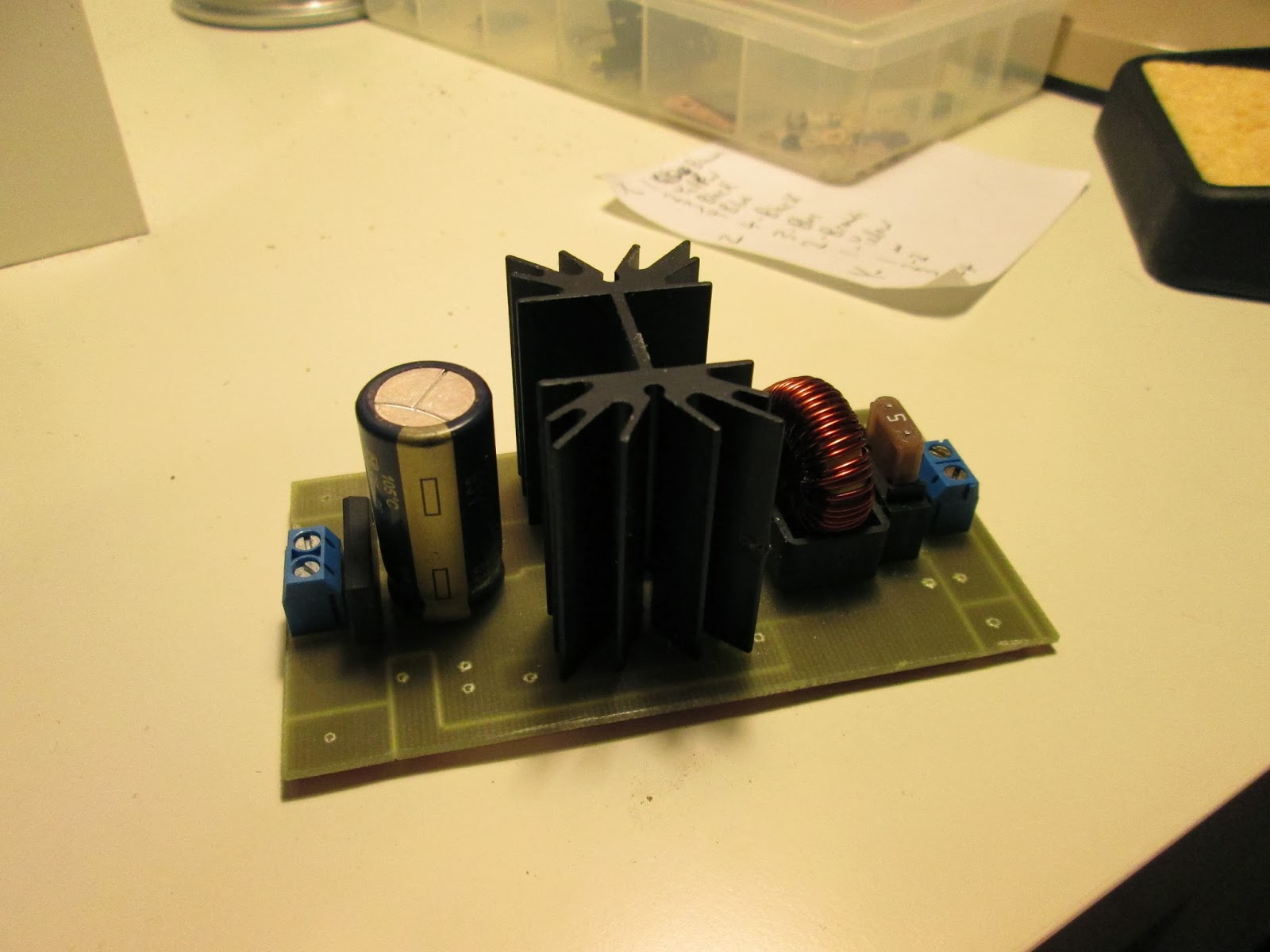
Revision 2.0 of the circuit board. The differences from version 1.0 are:
- PCB Mounted 15 Watt Heatsink (at 90% efficiency & 5A load, only 6-7 watt of dissipation needed)
- Mini ATO Automotive Type Fuse Holder (5A Fuse)
- New improved layout of components
- It actually works! Regulates voltage to ~12VDC.


Known problems with the circuit:
-TO-220 Package diode hole are obstructed by the headsink (as seen in the picture above)
-Tantalum capacitor still not in circuit (ran out of them from blowing them on the v1.0 pcb)

Hour meter at top of the picture reads 11.6 hours. I don't have that many hours on it. I've put about 2 hours on it since installing the meter on the blower. Below the hour meter is a DC lighted switch for the LED spot light.
LED light is mounted on the left side on the blower, but in retrospect the right side may have been better because of the location of the snow shout. It gives plenty of light for night work.

Sunday, January 5, 2014

Upgrading 3020 CNC Router Cables & Connectors - Part 2

The track for the Z-axis was just a tad wider than the existing track, so I was able to use the same mounting brackets and tray. I am using the same cable and track as I did for the lower chain in the previous post. The only difference is this chain is a little narrower (since it only has to pass two cables). 0.41" x 0.79" instead of  0.41" x 1.18". I also only purchased 2 feet.
http://www.mcmaster.com/#55835k34/=q4lpi9 
See Part 1 of the cable upgrade for more links on the cables & chains.

All of the bends were tight with the cable, but don't strain the steppers, or impede movement.
There is a slight problem with the power cable for the spindle motor. Since it moves up and down, there needs to be a certain amount of slack in the wires. I had to add (after this photo was taken) about 3-4" of wire to give it the necessary range of movement. Technically there should also be some kind of cable chain to serve the motor, but on a CNC this small, it's hard to find anywhere to mount it that doesn't interfere.
All axes hooked up the the control box with the next connectors and shielded cables.

Limit switches are probably going to be my next project.