Saturday, April 5, 2014

Harbor Freight Solar Panel Charge Controller

This is the charge controller included in the Harbor Freight 45W solar panel kit. The housing is a very nice aluminum extrusion which is also used as a heat sink for the electronics.


There are the following outputs on the unit:
- 5V USB
- Cigarette Lighter for the power inverter
- Cigarette lighter for 12 VDC
- 3.5mm jack for 3 VDC
- 3.5mm for 6 VDC
-  2x xxmm for 12 VDC


Model number of PCB: TPS-545-4A-02

Component List:

U1- ST LM393N - Dual voltage comparator
U2
U3 - not populated
U4
U5

Q1
Q2
Q3
Q4
Q5
Q6 - not populated

K1
K2
K3
9V - not populated
L-B-
3V
6V
USB
LED1
B-B+

C1
C2
C3 - not populated
C4 - not populated
C5 - not populated
C6

D1
D2
D3
D4
D5 - not populated
D6
D7
D8
D9
D10
D11
DZ - not populated

F1
F2 - to external ATO fuse

L1 - not populated
L2
L3 - shorted

R1
R2
R3
R4
R5
R6
R7
R8
R9
R10
R11
R12
R13
R14
R15
R16
R17
R18
R19
R20
R21 - not populated
R22 - not populated
R23 - not populated
R24

EL 817 Optocoupler

Update (May 11th, 2015):
I've discovered another website with more information on the controller as well as schematic. Please see the links below.
http://www.kiblerelectronics.com/corner/ccii_29.html
http://www.kiblerelectronics.com/corner/HF_charger_sch.pdf

Snow Blower Light & Voltage Regulator Functional!

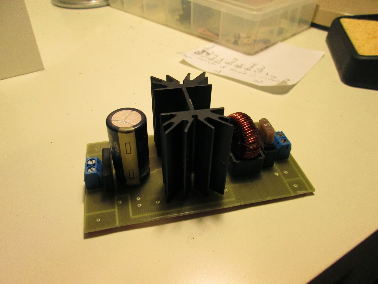
Revision 2.0 of the circuit board. The differences from version 1.0 are:
- PCB Mounted 15 Watt Heatsink (at 90% efficiency & 5A load, only 6-7 watt of dissipation needed)
- Mini ATO Automotive Type Fuse Holder (5A Fuse)
- New improved layout of components
- It actually works! Regulates voltage to ~12VDC.


Known problems with the circuit:
-TO-220 Package diode hole are obstructed by the headsink (as seen in the picture above)
-Tantalum capacitor still not in circuit (ran out of them from blowing them on the v1.0 pcb)

Hour meter at top of the picture reads 11.6 hours. I don't have that many hours on it. I've put about 2 hours on it since installing the meter on the blower. Below the hour meter is a DC lighted switch for the LED spot light.
LED light is mounted on the left side on the blower, but in retrospect the right side may have been better because of the location of the snow shout. It gives plenty of light for night work.

Sunday, January 5, 2014

Upgrading 3020 CNC Router Cables & Connectors - Part 2

The track for the Z-axis was just a tad wider than the existing track, so I was able to use the same mounting brackets and tray. I am using the same cable and track as I did for the lower chain in the previous post. The only difference is this chain is a little narrower (since it only has to pass two cables). 0.41" x 0.79" instead of  0.41" x 1.18". I also only purchased 2 feet.
http://www.mcmaster.com/#55835k34/=q4lpi9 
See Part 1 of the cable upgrade for more links on the cables & chains.

All of the bends were tight with the cable, but don't strain the steppers, or impede movement.
There is a slight problem with the power cable for the spindle motor. Since it moves up and down, there needs to be a certain amount of slack in the wires. I had to add (after this photo was taken) about 3-4" of wire to give it the necessary range of movement. Technically there should also be some kind of cable chain to serve the motor, but on a CNC this small, it's hard to find anywhere to mount it that doesn't interfere.
All axes hooked up the the control box with the next connectors and shielded cables.

Limit switches are probably going to be my next project.

Saturday, December 28, 2013

Voltage Regulator Installation & Problems

Problem #1:
Do not appear to be "regulating" the voltage. The voltage changes dramatically with a change in RPM of the engine.
Problem #2:
Extreme vibrations from the engine cause the heatsink to bend the switching voltage regulator's pins clear off of the board (see pictures). I need to redesign to have a heatsink which secures to the board.

Friday, December 27, 2013

Voltage Regulator for Tecumseh HMSK80 Alternator

Last winter I installed an alternator on my Tecumseh powered snow blower. I did design and build a circuit for the voltage regulator. I also purchased an LED flood light and mounted it to the blower. Here is the long awaited documentation and finishing of last years project!


TruckStar 12-24 Volt LED Flood Light - Clear, Round, 4in., Model# 1492115:


Claims a meager 1.06A of draw at 14.3VDC. Through 6x 3 Watt LED's it promises an impressive 1350 Lumens. I really like the quality of the unit. It's a solid metal case that's fully sealed. It's also quite slim, unlike a traditional flood light. I paid $59.99. It's regular price is $69.99. I have seen it for as low as $54.99 depending on the sale.

Voltage Regulator
Opted to go with the TI LM2677/8/9 5A Voltage regulator.
 http://www.ti.com/product/lm2677
It was the highest power voltage regulator I could find in a TO220 package. It's also sufficient power for my use. I used TI's special software (Power Stage Designer) to calculate the values of the inductor, capacitors, and resistors I needed for my specific requirements. I especially like that it's a switching regulator, not a linear regulator, so it's more efficient. TI claims up to 92% efficiency. This is the type of chip which could be used in high end computer power supplies.
Here is a generic example provided by TI:
This example gives 5V with a maximum current of 5A.
Using TI's online WebBench tool I input my requirements of 30-40V input and 24V, 5A output. It yielded this circuit:

To run the WebBench tool for yourself, go to the component page here:
http://www.ti.com/product/lm2677
On the right hand side you input your requirements and then click "Open Design". You will need to create a TI account and log in if you don't already have one (it's free).

Formerly I used TI's older software called "LM267X Made Simple" which is a download and install. It lets you choose your chip and also picks out the components you need. Both tools are nice because they generate a BOM for you.

With this schematic I made the following PCB layout:
 And the isolation routing for my CNC router:
There are some problems with the above PCB. Something is wrong with the Tantalum capacitor because I popped two of them almost immediately, however the circuit seemed to run fine without them. I'm not sure of the cause for this as of yet. I also screwed up my routing for the 3 resistors (I wanted to use 2 in series to get the correct resistance). Once I corrected the resistors, I was able to run my LED spot light with this circuit. I am currently in the process of making a 2nd revision of the circuit to address these two problems as well an incorporate a board mounted heatsink.

Quick BOM:
- U1 - LM2877 Switching Voltage Regulator - Sample
- L1 - Inductor 50uH 5A - Digikey #553-1121-ND
- Cin - Aluminum 1000uF 63V 20% - Digikey #P11280-ND
- Cout - Tantalum 47uF 20V 10% - Digikey #478-6065-ND
- Cb - Tracon 2A104K - Already Had
- D2 - Rectifier Bridge 10A 100V - Digikey #GBU1001DI-ND (not shown in TI schematic)
- D1 - STPS2045CT - Power Schottky Rectifier 2x10A 45V- Recycled from old computer PSU

- R1 - 1K
- R2 - 10K

Heatsink Selection:
The switching regulator is very efficient when compared to a traditional linear voltage regulator like the LM7805. The lowest efficiency it claims to get it better than 94%. This means when serving 5A of current at 24V (120W) it will need to dissipate ~7.2W. However, my light only pulls around 0.5A so we're talking much less. Never the less, we need to have a heatsink on our regulator.

How to calculate resistors:
See pages 15 & 16 of the datasheet: http://www.ti.com/lit/ds/symlink/lm2677.pdf
1K is recommended for R1
Using the formula provided, to get 14.4V one should use a 10.9K resistor for R2.

If I have made an mistakes above, please let me know and I will correct them. I hope this helps some people.


Thursday, November 28, 2013

7x Tailstock Cam Lock

This was my first complex project and I was learning many different machining processes in order to complete it. The hardest was to make the actual cam piece. Additionally, I attempted to do the project with easily obtainable, local, hardware store stock & pieces.

One overlooked piece is the bottom plate that slides in the lathe bed way. I have yet to see an aftermarket cam lock kit that includes an upgrade for this. They just use the existing plate which is prone to bending after regular use.

 This piece is the piston through which the cam turns. The bottom of the piston has a hole drilled and tapped to attach the bottom plate. The piston slides up and down inside of the main housing.
 The top is threaded for a 1/2" bolt.
 Main housing made of out of ?" hex stock. Bored ?" for the piston.
Piston inside of housing.
 1/2" bolt threaded into the piston. The bolt will join to the bottom plate.
Here the bottom plate is attached to the bolt and piston. The 1/2" drill bit is through the housing and piston where the camshaft will go.


Two pieces of bar stock are welded together to form the bottom plate.
The head of the nut had to be shaved to be flush with the plate.


Unlocked and then locked positions of the lever.


The camshaft dismantled. It uses two E-clips to keep it in place.